
Tập tin:Hall effect.png

Tập tin gốc (984×986 điểm ảnh, kích thước tập tin: 401 kB, kiểu MIME: image/png)
Tập tin này từ Wikimedia Commons. Trang miêu tả nó ở đấy được sao chép dưới đây. Commons là kho lưu trữ tập tin phương tiện có giấy phép tự do. Bạn có thể tham gia. |
| Đây là một hình ảnh đã được chọn làm hình ảnh chọn lọc và được giới thiệu trên Trang Chính của Wikipedia tiếng Việt. |
|
| Miêu tả |
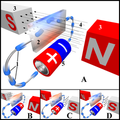
English: Shows the Hall effect for different directions of electric current and magnetic field. Legend:
In drawing "A", the Hall element takes on a negative charge at the top edge (symbolised by the blue color) and positive at the lower edge (red color). In "B" and "C", either the electric current or the magnetic field is reversed, causing the polarization to reverse. Reversing both current and magnetic field (drawing "D") causes the Hall element to again assume a negative charge at the upper edge. Deutsch: Diese Grafik illustriert den Halleffekt unter verschiedenen Richtungen des Elektronenflusses/des Magnetfeldes. Legende:
In Abbildung A wird im oberen Bereich ein Elektronenüberschuss (durch die blaue Farbe symbolisiert), im unteren Bereich ein Elektronenmangel (rote Farbe) erzeugt. In den Abbildungen B und C ist der Elektronenfluss bzw. der Magnet in eine andere Richtung gebracht worden, weshalb die Polarisierung des Hallelementes umgekehrt ist. Wird sowohl der Elektronenfluss als auch das magnetische Feld umgekehrt (Abbildung D), entsteht wie in Abbildung A ein Elektronenmangel im unteren Bereich.Français : Effet Hall pour différents sens du courant et du champ magnétique.
For more translations SEE BELOWLégende:
Dans le dessin A, une charge négative apparait à la bordure haute de l'élément (couleur bleue), et une charge positive à sa bordure basse (couleur rouge). En B et C, l'inversion du sens du courant ou de celui du champs magnétique provoque l'inversion de cette polarisation. En D, la double inversion du courant électrique et du champs magnétique donnent à l'élément la même polarisation qu'en A. |
||||||||
| Ngày | |||||||||
| Nguồn gốc | Tác phẩm được tạo bởi người tải lên | ||||||||
| Tác giả | Peo | ||||||||
| Giấy phép (Dùng lại tập tin) |
Tôi, người giữ bản quyền tác phẩm này, từ đây phát hành nó theo các giấy phép sau:
Bạn có thể chọn giấy phép mà bạn muốn. |
||||||||
| Phiên bản khác |
 only shows case A only shows case A |

Awards
Bức hình này đã được chọn làm hình ảnh của ngày trên Wikimedia Commons vào ngày 19 tháng 10 năm 2005. Dưới đây là lời mô tả: English: Hall effect Các ngôn ngữ khác:
Aragonés: Efeuto Hall Čeština: Hallův jev Deutsch: Illustration des Hall-Effekts Eesti: Hall'i effekti illustratsioon English: Hall effect Español: Ilustración del efecto Hall Français : L'effet Hall illustré Gaeilge: Iarmhairt Hall Galego: Efeto Hall. Latina: Hall effectus. Nederlands: Illustratie nl:Hall-effect Polski: Efekt Halla Português: Diagrama do efeito Hall Slovenščina: Hallov pojav Suomi: Hallin efekti Русский: Эффект Холла ไทย: ปรากฏการณ์ฮอลล์ 日本語: ホール効果 中文: 哈尔效应示意图 |
Deutsch: Dieses Bild wurde als Bild der Woche auf der tschechischen Wikipedia für die 1 Woche ausgewählt, 2007. English: This image was selected as a picture of the week on the Czech Wikipedia for 1st week, 2007. Français : Cette image est sélectionnée en tant qu’image de la semaine sur la Wikipédia Tchèque pour la 1e semaine de 2007. Italiano: Questa immagine è stata selezionata come Immagine della settimana su Wikipedia in ceco per la I settimana del 2007. Македонски: Сликава е избрана за слика на неделата на чешката Википедија за I недела од 2007 година. Русский: Эта иллюстрация была выбрана изображением недели в чешском разделе «Википедии» для недели номер 1 2007 года. Українська: Ця ілюстрація була вибрана зображенням тижня в чеському розділі «Вікіпедії» для тижня номер 1, 2007 року. |
Rendered using POV-Ray (see http://www.povray.org). The scene description "code" shown below supports rendering all of the four "situations" portrayed in the image - see the comment given in the code. The four images were subsequently combined, and the numbers and letters added, in a graphics software package. POV-Ray "code" for rendering all four parts of the illustration:
 /*
 ====================================================
 The Hall effect in metal under various circumstances
 ----------------------------------------------------
 Created by Søren Peo Pedersen - see my user page at
 http://da.wikipedia.org/wiki/Bruger:Peo
 ====================================================
 */

 #declare NorthAtLeft=no; // Orientation of magnetic field:
 // Use "yes" for north pole to the left, and south pole to the right
 // Use "no" for north pole to the right, and south pole to the left

 #declare PlusTowardsViewer=yes;  // Direction of current:
 // Use "yes" to have the positive pole at the ends of battery and Hall sensor nearest to viewer
 // Use "no" to have the negative pole at the ends of battery and Hall sensor nearest to viewer

 #declare PositiveCharge=no; // Polarity (color) of charge carriers in the circuit:
 // Use "yes" for orangeish colored charge carriers in wires and Hall sensor
 // Use "no" for light blue colored charge carriers in wires and Hall sensor

 #declare HallUpwards=yes; // Direction of sideways force upon charge carriers:
 // Use "yes" to have the charge carriers "bend upwards" inside Hall element
 // Use "no" to have the charge carriers "bend downwards" inside Hall element

 #declare NegativeEdgeUp=yes;  // Electrical polarization of Hall element (indicated by color):
 // Use "yes" to have bluish color at top of Hall element, indicating negative charge here
 // Use "no" to have reddish color at top of Hall element, indicating positive charge here

 #declare MagnetFont="arialbd.ttf" // Font for the "N" and "S" nomenclature on magnets

 // -----------------------------------------------------------------------------------------

 #declare txtNeutralElement=texture {  // Texture for electrically neutral parts of Hall element
   pigment {color rgbft <.5,.5,.5,1,0>}
   finish {
     reflection rgb .5
     phong 1
     metallic
     }
   }

 #declare txtNegativeElement=texture { // Texture for negatively charged parts of Hall element
   pigment {color rgbft <.1,.3,.9,1,0>}
   finish {
     reflection rgb <.1,.3,.9>
     phong 1
     metallic
     }
   }

 #declare txtPositiveElement=texture { // Texture for positively charged parts of Hall element
   pigment {color rgbft <.9,.3,.1,1,0>}
   finish {
     reflection rgb <.9,.3,.1>
     phong 1
     metallic
     }
   }

 #declare txtPolarisedElement=texture {  // Texture for polarized parts of the Hall element
   gradient y
   texture_map {
     [0 txtNegativeElement]
     [.5 txtNeutralElement]
     [1 txtPositiveElement]
     }
   translate <0,-.5,0>
   #if (NegativeEdgeUp)
     rotate <180,0,0>
   #end
   }

 #declare txtHallElement=texture { // Complete texture for the entire Hall element
   gradient z
   texture_map {
     [0 txtNeutralElement]
     [.5 txtPolarisedElement]
     [1 txtNeutralElement]
     }
   translate <0,0,-.5>
   scale 4
   }

 #declare WireTxt=texture {  // Texture for the wires connecting Hall element with power source
   pigment {color rgb .5}
   finish {
     reflection rgb .7
     phong 3
     metallic
     }
   }

 #declare Qtorus=intersection{   // 1/4 of a torus, for rounded "corner" on the wiring
   torus {1,.06 rotate <0,0,90>}
   box {-2,<2,0,0>}
   }

 #declare PlusPgmt=pigment {   // Pigment for positive end of the battery (power source)
   object {
     merge {
       box {<-.3,0, .35>,<.3,1,.45>}
       box {<-.05,0, .1>,<.05,1,.7>}
       }
     pigment {color rgb <1,0,0>}
     pigment {color rgb 1}
     }
   }

 #declare MinusPgmt=pigment {  // Pigment for negative end of the battery (power source)
   object {
     box {<-.3,0,-.55>,<.3,1,-.45>}
     pigment {color rgb <0,0,1>}
     pigment {color rgb 1}
     }
   }

 #declare PowerSource=union {  // Power source, symbolised by a battery
   merge {
     torus {.45,.05 rotate <90,0,0> translate <0,0,-.95>}
     cylinder {<0,0,-.95>,<0,0,.8>,.5}
     torus {.45,.05 rotate <90,0,0> translate <0,0, .8>}
     pigment {
       object {
         plane {<0,0,1>,0}
         pigment {PlusPgmt}
         pigment {MinusPgmt}
         }
       rotate <0,0,-35>
       }
     finish {ambient .4}
     }
   merge {
     torus {.35,.05 rotate <90,0,0> translate <0,0,-.95>}
     cylinder {<0,0,-1>,<0,0,-.9>,.35}
     torus {.35,.05 rotate <90,0,0> translate <0,0,.8>}
     cylinder {<0,0,.85>,<0,0,.8>,.35}
     difference {
       cylinder {<0,0,.85>,<0,0,.9>,.15}
       torus {.15,.05 rotate <90,0,0> translate <0,0,.9>}
       }
     cylinder {<0,0,.9>,<0,0,.95>,.1}
     torus {.05,.05 rotate <90,0,0> translate <0,0,.95>}
     cylinder {<0,0,.95>,<0,0,1>,.05}
     pigment {color rgb .5}
     finish {reflection rgb .9 phong 1 metallic}
     }
   }

 #macro txtChargeCarrier(Transparency) // Texture for charge carriers and their "motion blur tails"
 pigment {color rgbt <
   #if (PositiveCharge)
   1,.5,.2,Transparency
   #else
   .2,.5,1,Transparency
   #end
   >}
 finish {ambient .4}
 #end

 #declare FieldArrow=merge {   // Arrow indicating direction of magnetic field
   cylinder {<-2.5,0,0>,<2.3,0,0>,.003}
   cone {<2.3,0,0>,.05,<2.5,0,0>,0}
   pigment {color rgb 0}
   #if (NorthAtLeft)
   #else
   scale <-1,1,1>
   #end
   no_shadow
   no_reflection
   }

 #declare StraightCharge=union {   // Charge carrier with straight "motion blur tail"
   sphere {0,.15 texture {txtChargeCarrier(0)}}
   cylinder {0,<0,0,.499>,.15 hollow
     texture {
       gradient z
       texture_map {
         [0 txtChargeCarrier(0)]
         [1 txtChargeCarrier(1)]
         }
       scale .5
       }
     }
   no_shadow
   no_reflection
   }

 #declare CurvedCharge=union {   // Charge carrier with curved "motion blur tail"
   sphere {<0,-1,0>,.15 texture {txtChargeCarrier(0)}}
   difference {
     torus {1,.15 rotate <0,0,90>}
     plane {<0,0,1>,0}
     plane {<0,0,-1>,0 rotate <-29.99,0,0>}
     hollow
     texture {
       radial
       texture_map {
         [0 txtChargeCarrier(.3)]
         [1 txtChargeCarrier(1)]
         }
       frequency 12
       rotate <0,0,90>
       }
     }
   no_shadow
   no_reflection
   }

   // The scenario:
   box {<-.16,-1,-2>,<.16,1,2>   // The hall element
     texture {txtHallElement}
     no_shadow
     }

   merge { // Wiring with travelling charge carriers
     // Wiring on the side towards the viewer:
     cylinder {<0,0,-2>,<0,0,-3>,.06}
     #object {Qtorus rotate <90,0,0> translate <0,-1,-3>}
     cylinder {<0,-1,-4>,<0,-2,-4>,.06}
     #object {Qtorus translate <0,-2,-3>}
     cylinder {<0,-3,-3>,<0,-3,-1>,.06}
     // Wiring on the side facing away from the viewer:
     cylinder {<0,-3, 1>,<0,-3, 3>,.06}
     #object {Qtorus rotate <-90,0,0> translate <0,-2,3>}
     cylinder {<0,-1, 4>,<0,-2, 4>,.06}
     #object {Qtorus rotate <180,0,0> translate <0,-1,3>}
     cylinder {<0,0, 2>,<0,0, 3>,.06}
     texture {WireTxt}
     }

   union { // Charge carriers:
     // Charge carriers on the side towards the viewer:
     #object {StraightCharge translate <0,-3,-2.7>}
     #object {CurvedCharge rotate <30,0,0> translate <0,-2,-3>}
     #object {CurvedCharge rotate <90,0,0> translate <0,-2,-3>}
     #object {StraightCharge rotate <90,0,0> translate <0,-1,-4>}
     #object {StraightCharge rotate <90,0,0> translate <0,-1,-4>}
     #object {CurvedCharge rotate <150,0,0> translate <0,-1,-3>}
     #object {StraightCharge rotate <180,0,0> translate <0,0,-2.5>}
     // Charge carriers inside Hall element:
     #if (HallUpwards)
       #object {CurvedCharge rotate <195,0,0> translate <0,-.3,0>}
       #object {CurvedCharge rotate <30,180,0> translate <0,1.15,-1.5>}
       #object {CurvedCharge rotate <0,180,0> translate <0,1.15,1.5>}
     #else
       #object {CurvedCharge rotate <210,0,0> translate <0,-1,-1.5>}
       #object {CurvedCharge rotate <15,180,0> translate <0,.3,0>}
       #object {CurvedCharge rotate <180,0,0> translate <0,-1,1.5>}
     #end
     // Charge carriers on the side facing away from the viewer:
     #object {StraightCharge rotate <180,0,0> translate <0,0,3>}
     #object {CurvedCharge rotate <270,0,0> translate <0,-1,3>}
     #object {StraightCharge rotate <270,0,0> translate <0,-2,4>}
     #object {CurvedCharge rotate <330,0,0> translate <0,-2,3>}
     #object {StraightCharge translate <0,-3,2.3>}
     #if (PlusTowardsViewer)
       scale <1,1,-1>
     #end
     }

   #object {PowerSource  // The battery symbolising the power source of the circuit
       #if (PlusTowardsViewer) scale <1,1,-1> #end
       scale 2
       translate <0,-3,0>
       }

   #union {    // Pair of magnets
     // The magnet at the left-hand side of the image:
     box {<-15,-1,-1>,<-3,1,1>
       pigment {
         object {
           text {ttf MagnetFont
             #if (NorthAtLeft) "N" #else "S" #end
             ,3,0
             scale 2
             translate <-4.3,-.7,-1.5>
             }
           #if (NorthAtLeft)
             color rgb <1,0,0>
             color rgb .85
           #else
             color rgb .85
             color rgb <1,0,0>
           #end
           }
         }
       finish {ambient .4}
       no_shadow
       no_reflection
       }
     // The magnet at the right-hand side of the image:
     box {<3,-1,-1>,<15,1,1>
       pigment {
         object {
           text {ttf MagnetFont
             #if (NorthAtLeft) "S" #else "N" #end
             ,3,0
             scale 2
             translate <3.2,-.7,-1.5>
             }
           #if (NorthAtLeft)
             color rgb .85
             color rgb <1,0,0>
           #else
             color rgb <1,0,0>
             color rgb .85
           #end
           }
         }
       finish {ambient .4}
       no_shadow
       no_reflection
       }
     }

 // 4 x 4 arrows to indicate the direction of the magnetic field:
 #local Ktal=-.75;
 #while (Ktal<1)
   #local Rtal=-.75;
   #while (Rtal<1)
     #object {FieldArrow translate <0,Rtal,Ktal>}
     #local Rtal=Rtal+.5;
   #end
   #local Ktal=Ktal+.5;
 #end

 // Point of view:
 camera {
     location <4,3,-5>
     look_at <.8,-1.3,0>
     }

 // Illumination:
 light_source {<20,10,-15> color rgb 1}
 light_source {<-10,20,10> color rgb 1}

 // Spotty surroundings outside viewfield to enhance reflective surfaces:
 #declare Spotty=pigment {
   marble
   color_map {
     [0 color rgb 0]
     [1 color rgb .8]
     }
   scale .1
   }

 sky_sphere {
   pigment {
     gradient z
     pigment_map {
       [0.00 Spotty]
       [0.88 Spotty]
       [0.88 color rgb 1]
       [1.00 color rgb 1]
       }
     translate -.5
     scale 2
     rotate <35,-32,0>
     }
   }
Lịch sử tập tin
Nhấn vào ngày/giờ để xem nội dung tập tin tại thời điểm đó.
| Ngày/giờ | Hình xem trước | Kích cỡ | Thành viên | Miêu tả | |
|---|---|---|---|---|---|
| hiện tại | 03:00, ngày 10 tháng 4 năm 2005 | | 984×986 (401 kB) | Peo~commonswiki | Shows the Hall effect for different directions of electric current and magnetic field. |
Trang sử dụng tập tin
Sử dụng tập tin toàn cục
Những wiki sau đang sử dụng tập tin này:
- Trang sử dụng tại ar.wikipedia.org
- Trang sử dụng tại ast.wikipedia.org
- Trang sử dụng tại az.wikipedia.org
- Trang sử dụng tại be.wikipedia.org
- Trang sử dụng tại bg.wikipedia.org
- Trang sử dụng tại ca.wikipedia.org
- Trang sử dụng tại cs.wikipedia.org
- Trang sử dụng tại da.wikipedia.org
- Trang sử dụng tại de.wikipedia.org
- Trang sử dụng tại el.wikipedia.org
- Trang sử dụng tại en.wikipedia.org
- Trang sử dụng tại en.wikiversity.org
- Trang sử dụng tại es.wikipedia.org
- Trang sử dụng tại fa.wikipedia.org
- Trang sử dụng tại fi.wikipedia.org
- Trang sử dụng tại fr.wikipedia.org
- Trang sử dụng tại fr.wikisource.org
- Trang sử dụng tại fr.wikiversity.org
- Trang sử dụng tại he.wikipedia.org
- Trang sử dụng tại hr.wikipedia.org
- Trang sử dụng tại hu.wikipedia.org
- Trang sử dụng tại hy.wikipedia.org
Xem thêm các trang toàn cục sử dụng tập tin này.